Intel FPGA 基于NIOS的串口远程升级

本文介绍一种基于串口远程升级Intel FPGA的方法,在Intel FPGA运行NIOS,上位机通过串口连接NIOS对FLASH进行操作,上传用户的新FPGA设计,通过擦除重写FLASH,来达到更新Intel FPGA程序的目的。
此应用主要面向有二次升级需求的用户。例如产品出厂之后,客户需要进行刷机更新,就可以采用这个方案,将最新的程序放在官网给客户下载之后,通过串口自行升级。再例如整机装配之后,不方便留调试AS/JTAG口,就可以留串口,利用本文提供的方法进行整机调试过程中的程序更新升级。本文篇幅较长,全文目录如下:
一、实验要求以及方案信息
实现本文实验的要求:
- Cyclone IV EP4CE10E22C8 开发板
- Intel Quartus Prime 17.1
- USB转RS232 串口线
- 二进制/十六进制文本编辑器
方案信息:
占用资源:LE≤3610、PLL 1个、Memory 87056bits
Flash型号:MT25QL128ABA1ESE-0SIT 128MB SOP-8
二、参考例程文件
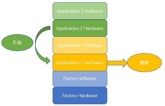
参考例程包含一个原厂镜像(Factory Image),两个应用镜像(Application Image),以及各自对应的NIOS软件程序(NIOS II Software)。包含下载所需的JIC文件,以及合成JIC需要的SOF和HEX文件,升级需要的RPD文件。
升级文件列表如下所示:
| 文件名称 | 描述 |
|---|---|
Factory.zip Application1.zip Application1.zip | 三个工程的压缩包 |
| \Factory\output_files\output_file.jic | 合成的JIC文件 |
\Factory\software\factory\mem_init\epcq_controller.hex \Application_1\software\app1\mem_init\ epcq_controller.hex \Application_2\software\app2\mem_init\ epcq_controller.hex | Factory和APP1、APP2的hex文件 |
| \RPD_Data\App2_hw.rpd | APP2的FPGA升级文件 |
\Factory\output_files\Factory.sof \Application_1\output_files\application_1.sof \Application_2\output_files\application_2.sof | Factory和APP1、APP2的sof文件 |
三、框图
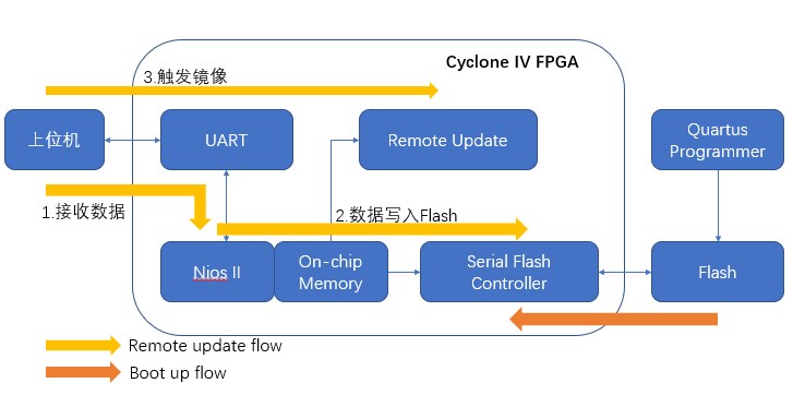
四、例程设置
4.1 下载文件生成
1、SOF文件生成
FPGA文件编译完成之后就可以生成。
2、HEX文件生成
- 在Quartus 菜单栏上打开“Tools”下的“Nios II Software Build Tools for Eclipse”。
- 在弹出的Workspace Launcher中选择Factory文件夹中的“Software”文件夹,单击OK。
- 右击factory_bsp,选择build project。
- BSP build complete之后,右击factory,单击build factory。
- factory build complete之后,右击factory,单击make targets,选择build。
- 在Make Targets 中选择mem_init_genertate,单击Build。
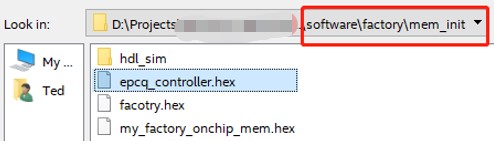
- 生成的HEX文件在\Factory\software\factory\mem_init 文件夹下,epcq_controller.hex(可修改为factory.hex)。
4.2 下载文件合成
1、在Quartus的Files里面打开 “Convert Programming Files…”
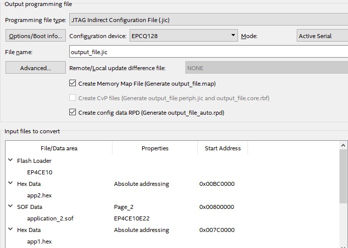
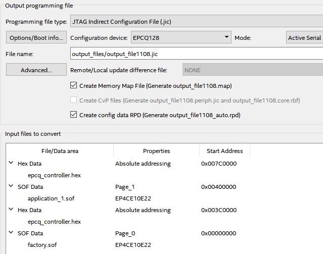
2、在 “Output programming file” 选项卡, 设置一下项目:
- Programming file type: JTAG Indirect Configuration File (.jic)
- Configuration device: EPCQ128 (select according to your EPCQ type)
- Mode: Active Serial
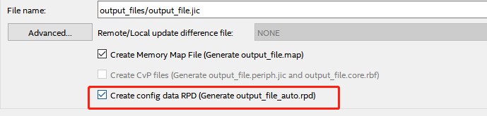
- File name: You may select your preferred path for the output file (.jic).
3、勾选 “Create config data RPD (Generate output_file_auto.rpd)”。
4、在“Input files to convert” 选项卡, 按照以下步骤进行设置:
- 选择 “Flash Loader”,单击 “Add Device”, 选择Cyclone IV里面的“EP4CE10” 。
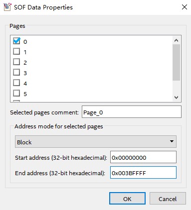
- 对于原厂镜像的FPGA SOF文件,需要设置如下:
i. 选择“Page_0” 然后单击“Properties”。
ii. 选择“Address mode for selected pages” 里面的“Block”。。
iii. 设置“start address”为“0X00000000”,设置“end address”为“0X003BFFFF。
iv. 单击“Add File”,然后将原厂镜像的SOF文件“Factory.sof”添加进来。
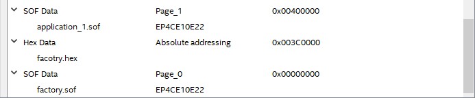
- 对于Application_1,设置如下:
i. 单击“Add Sof Page”。
ii. 选择“Page_0” 然后单击“Properties”。
iii. 选择“Address mode for selected pages” 里面的“Block”。
iv. 设置“start address”为“0X00400000”,设置“end address”为“0X007BFFFF。
v. 单击“Add File”,然后将SOF文件“Application_1.sof”添加进来。
- 同理,将Application_2的“start address”为“0X00800000”,设置“end address”为“0X00BBFFFF”。
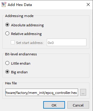
- 对于原厂的nios 程序文件,需要设置如下:
i. 单击“Add Hex Data”,打开对话框。
ii. 单击“Hex file”框后面的省略号,选择生成的factory.hex文件。
5、最后单击Generate,生成JIC文件。
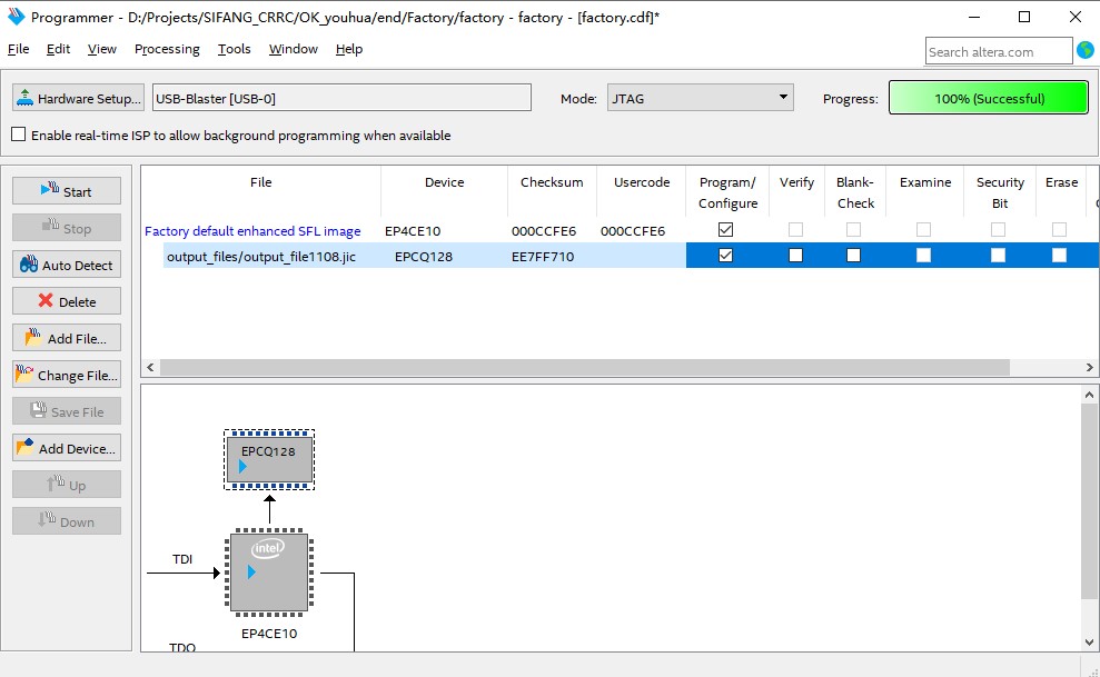
4.3 下载FPGA镜像和nios ii 软件镜像
- 连接USB Blaster,板子上电。
- 从“Tools”打开“Programmer”,点击“Hardware setup……”,选择“USB-Blater II”。
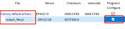
- 点击“Auto Detect” 选择“EP4CE10”。
- 点击“File”,选择生成的JIC文件。同时在“Program Configure”打钩。
- 打开“Tools”里面的“Options……”,在“Unprotect EPCS/EPCQ devices selected for the erase/program operation”选项打钩。
- 点击“Start”,开始下载,下载完成后,板子重新上电。
4.4 生成升级RPD文件
我们在生成JIC文件的时候,同时生成了RPD(Raw Programming Data)文件,我们的升级文件需要从RPD文件中截取出来。
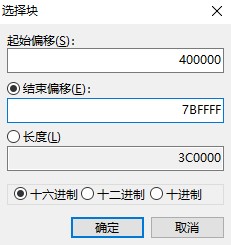
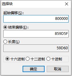
- 利用文本编辑器将生成的“output_file_auto.rpd”文件打开,在“‘编辑“菜单下,选择“选择块”,打开对话窗口。
- 对于Application_1,FPGA程序对应地址范围:0x00400000 – 0x007BFFFF,在“选择块”的窗口的起始偏移中,填入“400000”,在结束偏移中填入“7BFFFF”,单击确定,选择数据。
- 在选择的数据上右键选择“复制”。
- 单击“新建”,右键选择“插入式粘贴”,在弹出的改变文件大小提示对话框中选择“确定”。
- 选择“文件”菜单下的“另存为”,选择合适位置,存为“app1_hw.rpd”。
重复上述步骤,根据下面的表格中所列出的起始偏移地址和结束偏移地址,截取出Application_1的NIOS程序,Application_2的FPGA程序和NIOS程序。
程序占用空间列表如下所示:
| 名称 | 大小(KB) | 地址范围 |
|---|---|---|
| Application 2 software | 256 | 0X00BC0000-0X00BFFFFF |
| Application 2 hardware | 3840 | 0X00800000-0X00BBFFFF |
| Application 1 software | 256 | 0X007C0000-0X007FFFFF |
| Application 1 hardware | 3840 | 0X00400000-0X007BFFFF |
| Factory software | 256 | 0X003C0000-0X003FFFFF |
| Factory hardware | 3840 | 0X00000000-0X003BFFFF |
请确认生成的RPD文件有着正确的文件大小。
五、运行
1、连接USB转RS232串口线,连接USB Blaster II,板子上电。
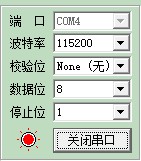
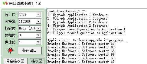
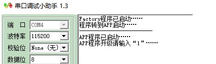
2、打开串口调试助手(理论上任一串口调试皆可,但实际操作中发现有些软件是不行的,如果有发不出数据的情况,可以考虑换一个串口调试助手)。打开串口的设置,设置波特率“115200”,校验位“None”,数据位“8”,停止位“1”。
3、程序跳转
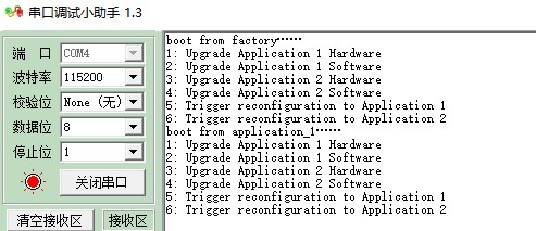
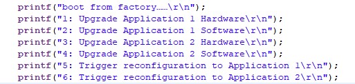
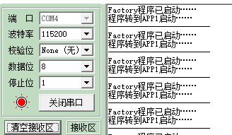
重新上电,会在接收区看到打印信息,可以看到程序从Factory启动。
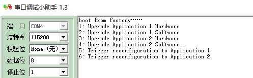
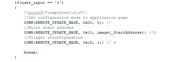
- 从串口发送字符“5”,从打印信息中看到程序从Factory镜像转到Application_1镜像启动。
重新上电,同样操作,串口发送6,程序会从Factory镜像转到Application_2启动。
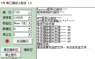
4、串口远程更新,本次更新将Application1的hardware擦除,然后将Application2的hardware更新到被擦除的区域。
- 重新上电,发送1,可以看到Flash相关区域(Application1的hardware)已经被擦除。
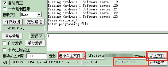
- 在串口调试助手上面的“选择发送文件”,选择之前生成的Application2的hardware文件,点击串口调试助手的“发送文件”选择发送。可以看到下面的发送窗口已经开始发送了。需要等待十分钟左右,等待发送完成。
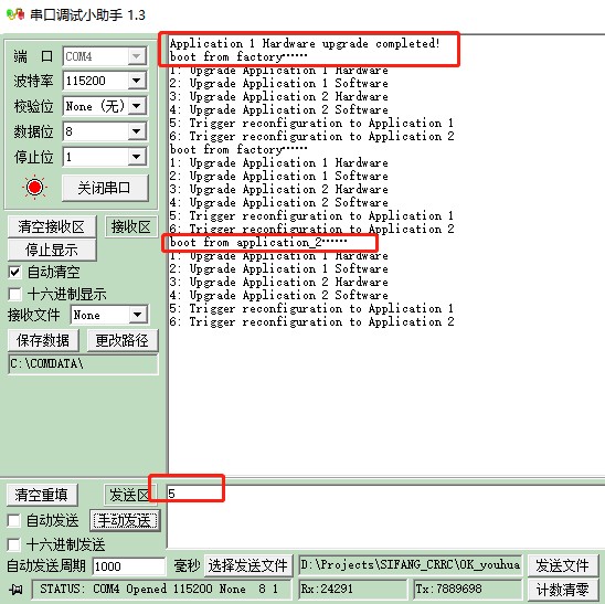
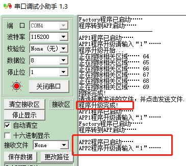
- 待发送完成之后,会提示“Application 1 Hardware upgrade completed!”,但此时程序还是会打印程序从Factory启动,待重新上电后,发送“5,”,会提示程序从Application2启动(正常情况下会提示从Application1启动),升级成功。
六、实际应用
6.1 修改例程
实际应用中,我们可能用不到3个镜像的情况,更多的是2个镜像,可以随时通过串口升级软硬件程序即可,并且不用到NIOS的话,NIOS程序一般不需要升级,可以关闭NIOS升级入口。后期升级维护更多的是现场人员,为了防止误操作和缩短升级的时间,我们将程序稍加改动,让串口界面清晰明了,让程序升级人员更容易操作。
1、语言汉化
将串口打印信息汉化一下,例如:将之前的Factory打印信息修改
修改为:
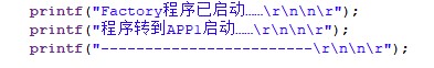
- 具体的代码请见工程。
2、NIOS程序去冗余
- 在Factory程序中,只起到跳转的作用,所以可以将APP1&2的Hardware、Software升级功能去掉。
- 在APP1中,不必使用跳转功能,可以将跳转功能去掉,将APP2的有关升级代码去掉。
- 具体的代码请见工程。
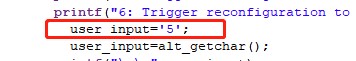
3、上电即跳转
上电之后,FPGA默认从0地址启动,即程序会默认从Factory程序启动,然后从原厂程序跳转到APP1启动。在上面的教程中,我们是通过发送“5”来进行跳转,现在我们在Factory程序中,直接将input置为5,这样就可以上电之后,先从Factory启动,然后跳转到APP1启动。
4、缩小升级文件
- 对于生成的RPD文件,不全是有意义的数据,空余的地方使用0XFF填充。
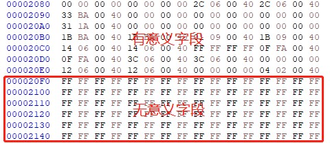
- 举例来说,存放APP1 Hardware地址段0X00400000-0X007BFFFF中,并不全是有效字段,我们截取出来的RPD文件,包含许多无效字段,所以我们剔除无效字段,留下有效的就可以。

- 注意在有效数据结束的时候,地址位选择是0X00859D5F而不是0X00859D50,所以文件长度即为59D5F。选择块,复制,另存为相应的RPD文件即可。
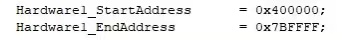
- 在NIOS程序里面,地址也要做相应的修改。修改地址之后,擦除的区域也会相应改变。
修改为:

6.2 实际应用操作
1、板子上电,打开串口,配置。
2、Generate JIC文件配置如下:
3、下载JIC文件,重上电。打印信息如下:
4、串口发送1,则会显示擦除相关区域,然后选择相应的文件,并且发送。
5、等待几分钟后,显示程序升级完成。重上电之后,显示程序已经从APP2启动,升级成功。
6.3 实际应用容易出现的问题以及避免
在上述实际应用中,要求务必一次升级成功。一旦升级失败,就是出现错误导致无法再次升级。因为在Trigger IP Remote Update中设定,一旦升级失败,会跳转到Factory程序执行,但是我们在Factory程序中已经设定直接跳转到APP1,而APP1因为升级失败而无法正常启动,又会跳转回到Factory程序,所以如果升级失败,将是一个死循环。
为了避免出现此类情况,建议在外部放置一个拨码开关,上电之后检测拨码开关的设置来决定从哪个程序启动。例如开始设置:3‘b001:从Factory启动’,如果升级完APP1(可以多次升级,直至升级成功),则设置3‘b002,从APP1启动。
七、常见错误/问题
7.1 新建NIOS II 软件程序
当想把RSU程序移植到其他器件上的时候(尤其是不同系列的器件),尽量不要只通过修改Device来实现,容易出现一些莫名其妙的编译错误。要按照例子工程,重新添加IP,重新新建NIOS II软件程序。
新建NIOS II软件程序遵循以下步骤:
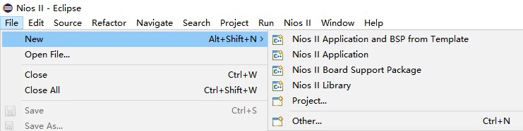
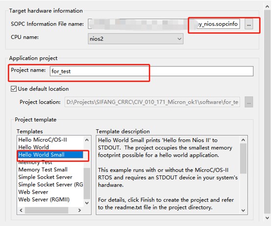
1、“File”-“New”-“Nios II Application and BSP from Template”
2、在弹出的窗口“SOPC Information File Name” 中,选择对应的SOPCINFO文件。Nios II IDE使用.sopcinfo文件来信息来为目标硬件编译软件程序。
3、在“Project Name”输入工程的名字,注意不要有空格
4、在“Templates”中选择“Hello World Small”。
5、点击“Next”创建BSP工程。
6、点击Finish完成工程的创建。
7.2 Scanf函数
在7.1的“Templates”中,可以选择“Hello World”或者“Hello World Small”。后者是前者的简化版,支持的功能少,占用的体积更小。如果片子片上资源够大,考虑前者,如果资源较少,考虑后者。例如“EP4CE10”,前者占用资源太多放不下,只能考虑后者。
在“Hello World Small”中,不支持函数“Scanf”,编译会出现以下错误:
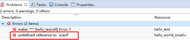
此种情况下,我们用“Alt_getchar()”函数代替。
在程序中,相应的做出修改。
scanf("%2x%2x%2x%2x", &receivedHex[0], &receivedHex[1], &receivedHex[2], &receivedHex[3]);
修改为
for(int i=0;i<4;i++)
receivedHex[i]=alt_getchar();
7.3 UART指向
1、在NIOS工程里面,串口有两个,JTAG UART和UART。
JTAG UART是要自己添加的Quartus内置IP核,通常用来是实现PC和Nios II系统间的串行通信接口,它用于字符的输入输出。
在Qsys中添加了JTAG UART核 ,而在系统生成,例化中并没有关于JTAG UART的端口, 这部分接口软件内部自动添加,就像你不需要在顶层分配EPCS接口,只要你在你的调试代码中调用了打印信息的调试函数就可以。
UART就是我们普通的串口,通过RS232与PC相连。
2、在调试过程中,我们根据调试需要来切换不同的串口。
在BSP Project 右键,选择“NIOS”-“BSP Editor”。
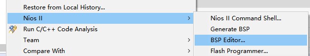
- 在打开的窗口中选择“Common”-“hal”-“stdin”,可以选择UART或者JTAG UART。
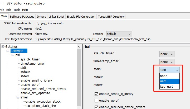
- 选择了“Jtag_uart”,串口信息打印在NIOS的Console窗口,选择“uart”,串口信息打印在PC的串口调试助手上。
7.4 写保护开关
在NIOS程序中,下面语句是EPCQ Controller(Intel FPGA Serial Flash Controller Core) 对Flash的开关写保护操作。
IOWR(EPCQ_CONTROLLER_AVL_CSR_BASE, 0x3, 0x00001703);
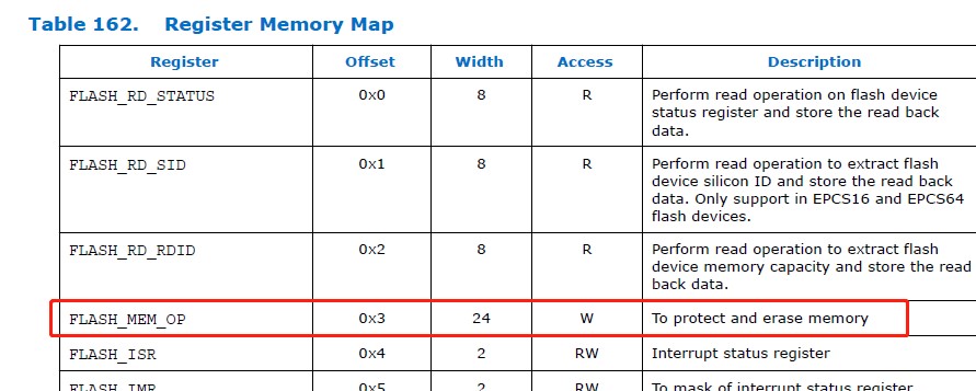
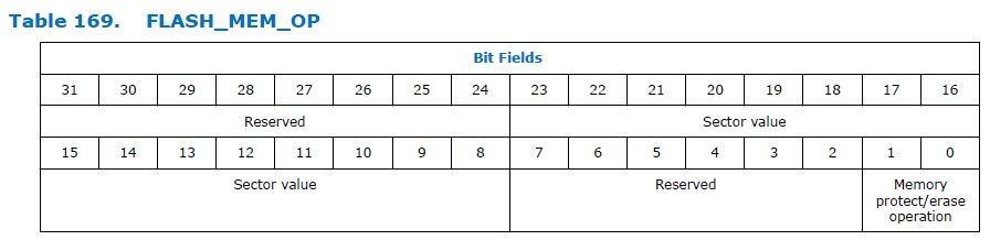
通过上图可以看到,FLASH_MEM_OP[31:24],FLASH_MEM_OP[7:2]是保留字,不能够操作,我们能操作的是FLASH_MEM_OP[23:8]和FLASH_MEM_OP[1:0]。
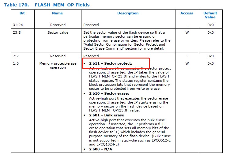
对于FLASH_MEM_OP[1:0],选择2‘b11。
对于FLASH_MEM_OP[23:8],我们要操作的也只是低五位,即FLASH_MEM_OP[12:8]。位13到位23是保留的,应该设置为零。低五位提供Flash扇区的组合值,对不同扇区进行操作。
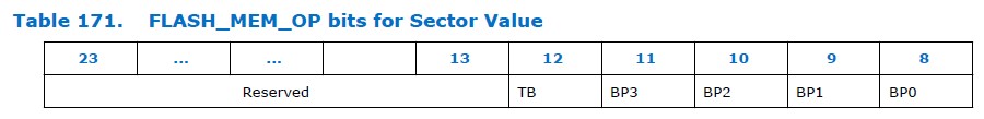


从上图可以看出,我们选择的是1001-所有扇区全部保护和0111,保护低位扇区(因原厂程序存在0地址低扇区,所以升级过程中,原厂程序不能被删除)。对应的寄存器0X00001903和0X00001703。
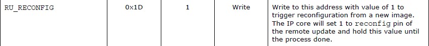
7.5 Remote Update IP
Remote Update IP 从Flash中将升级的镜像下载到FPGA,然后更新配置电路,来启动重配置。
在配置过程中和配置之后,Remote Update 执行错误检测,当检测到错误时,直接恢复到出厂程序运行,并且提供错误状态信息。
在NIOS程序中,需要操作的寄存器有 0X0C、0X10、0X1D(仅限于Cyclone IV和Cyclone 10 LP,其他系列的根据datasheet来定)。


7.6 数据截取文件从RPD而非JIC
注意数据截取的时候是从RPD文件,而非JIC文件,从JIC文件截取是会出错的。RPD文件在生成JIC的文件一起生成的。
7.7 SOF、JIC、ELF、HEX
1、文件类型
- SOF:SRAM Object File
- JIC:JTAG Indirect Configuration File
- HEX:Hexadecimal (Intel-Format) Output File
2、本文用到的是SOF+HEX=JIC,然载JIC的方式
- SOF文件是由FPGA编译产生。
- HEX文件是由NIOS编译产生,编译方法请见上文。
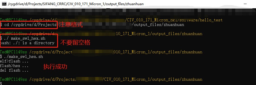
- HEX文件也可以通过ELF文件转换而来。转换指令
elf="sw.elf"
echo "elf>flash ..."; elf2flash --epcs --input=$elf --output=sw.flash
echo "flash>hex ..."; nios2-elf-objcopy --input-target srec --output-target ihex sw.flash sw.hex
echo "del flash ..."; rm -f *.flash
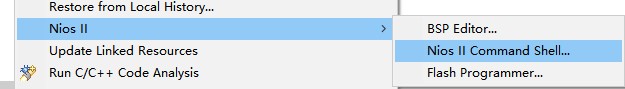
上述指令存为elf2hex.sh文件,通过Nios II command shell 执行。在NIOS project右键,选择“Nios”-“Nios II Command Shell”
执行命令如下图所示,另外注意这种生成的HEX文件方法仅供参考。
7.8 NIOS调试以及下载
在实际项目开发中,不必每次都合成JIC文件下载,可以先由NIOS里面直接下载,方便调试。
- Nios Project-右键,然后选择“Run as”-“Run Configurations”,打开配置窗口。
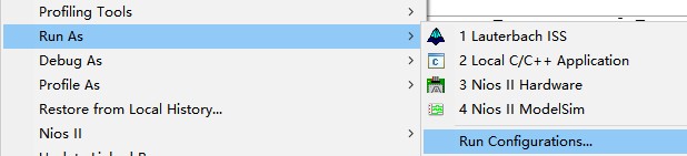
- 在配置窗口“Project”-“Project ELF file name”中选择正确的ELF文件。
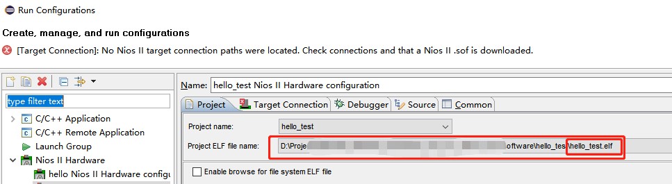
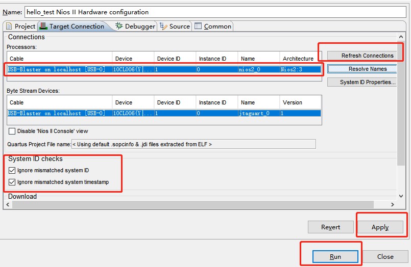
- 在“Target Connection”中,可以看到cable的正确连接,如果没有正常连接,点击右侧的“Refresh Connections”即可出现。另外在下面的“System ID checks”选项卡全部勾选,选择忽略System ID和timestamp的检查,点击“Apply”-“Run”。
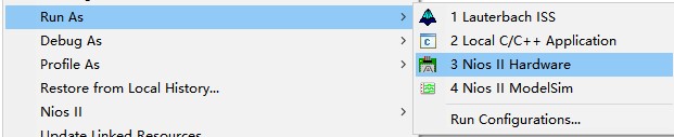
- 如果已经配置过,下次我们可以在Nios Project上右键,然后选择“Run as”-“Nios II Hardware”,不必每次都配置。
八、总结
上文主要介绍了基于串口远程升级Intel FPGA的方法,详细介绍了各部分的功能,JIC文件的生成,Flash的操作,寄存器的配置等,最后从实际应用角度出发,做了可以应用到实际工程的DEMO,并对可能出现的各种状况做了解析以及应对方法,读者可以根据本文的步骤以及DEMO,可以稍作修改,即可以简单的应用到自己的实际工程中。假如您对此应用感兴趣,请点击下方「联系我们」,提交您的需求,我们骏龙科技公司愿意为您提供更深入的讲解与介绍。
更多信息:
相关链接
Copyright 2026 Macnica Cytech Limited